The N-channel depletion mode MOSFET operations results in a load current independent of the applied drain-to-source input voltage. To turn off a depletion-mode MOSFET the V GS should be lower than the (negative) V GS(th). Therefore, even at V GS of 0 V, a depletion type MOSFET can conduct current. For an N-channel enhancement MOSFET V GS(th) is above 0 V.

Hope this helps, and good luck with your project.For a MOSFET, the gate-to-source voltage (V GS) should be higher than the gate-to-source threshold voltage (V GS(th)) in order to conduct current through it.
#Mosfet n type download
For example, if you go to and download app note AN9010, there's a good introduction to how MOSFETs work. If you're new to this aspect of electronics, one great resource is the application notes manufacturers publish, they want to help you use (and buy) their parts. Te transient thermal impedance spec will help you there.Īlso, if you're driving an electromagnet, that's a big inductor, and when you switch current there will be large voltage spikes which can easily damage the part, so you need to clamp that. While the gate current is negligible, there's a very large capacitance that needs to charge (look at the gate charge and input and output capacitance in the spec), and when it's between all the way on and all the way off it will dissipate lots of power, so you usually want to make that transition quickly, though with a 100 Hertz rate that's probably not going to too bad. Can you use the 5V Arduino logic to turn on this N-MOSFET and let a 12V VIN pass through to then trigger the bigger transistor?ġ00 Hertz is trivial for this part, it has a turn on time of 140 nanoseconds and turn off time of 100 nS, but you need to drive the gate properly.
#Mosfet n type how to
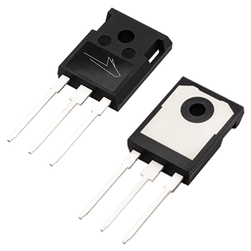
I think I need a heavier duty transistor to solve this, but I've no idea which one (someone here mentioned IRFP260?) and with these higher-power ones, how to drive them w/ Arduino logic.
#Mosfet n type full
Can someone help me with some suggestions? I thought maybe a relay, but I definitely need to run this at all ranges of current between full load and just a little bit so i think a relay won't be able to switch fast enough to give enough resolution on the duty cycle, no? So I think things get complicated when you want way more power.

Now, though, I'm trying to make a basic electromagnet (use an Arduino to slowly turn it on & off using a changing duty cycle) and I'm burning these things, my Arduino, and my board up I think for 2 reasonsġ) I'd LIKE to run 12-24V at ~10Amps and the dissipation on these is 96W I tried running multiple of these in parallel but no luck eventhough they're supposed to be self-balancing as they get hotter.Ģ) This MOSFET gets stuck in the open phase i think if the duty cycle is too high, the 0 or 5V Arduino logic can't seem to turn off the MOSFET when the 12V & 8A is going through. I love these- been using them w/ Arduino to drive multiple 12V LED strips. What the hell is wrong with these mosfets? They are really setting my projects back. I hooked them up properly, heat skined them. So when the voltage at the gate was zero, 6 amps were running through the mosfet. 40% of the current I was running through it. They are rated for 30 amps right? Well ran 20 amps through one, and after a few cycles. I had 2 left, and I was building a motor controller. Well 2 of them broke int hat case, they would not close the damn circuit! They leaked 10% of the current I was running through them.

I had 4 left, and I used them for some bread board prototyping. All the mosfets started to leak current, well 4 of them I used for the inverter. I built a light duty inverter with them, pushing no more than 1 amp at 5 volts. A dollar for a 30 amp mosfet? Wow, that was a great deal. Well, These mosfets looked like a great deal when I first saw them.


 0 kommentar(er)
